Matthew Heydman's
Digital Audio
Resource Pages
|
|
XLR > RCA Attenuator
| PROBLEM: |
When recording from a soundboard/mixing console, the XLR output signal
is too strong for a tape deck's inputs and results in distortion. |
| SOLUTION: |
Attenuate the signal between the board's output and the deck's input. |
"Cool," you say, "So what do I do? Just put a volume knob on my patch cable?"
Unfortunately, it's not that easy. But it isn't very difficult, either. Below are
plans on building such a device. Please understand that I am no technical genius,
electromagical engineer like some DAT Heads, or anything other than
just some guy who had the problem outlined above and figured out how to solve it.
Because of this, I can take no responsibility for anything that might happen to you
or your deck that results from the use of this device. FWIW, I've been using one of
these for many years with no problems.
 Parts List Parts List
The following is a list of parts that can be purchased at a Radio Shack. It's
everything you need to build the project, and then some. You see, some of the parts
are more easily purchased in "value-packs", which include other stuff you don't need.
If you can find these parts sold individually, more power to you.
I 'm assuming that you already have XLR cables and XLR-to-1/4" adapters as part
of your cable/adapter collection. If not, these can also be purchased at Radio Shack.
I also assume that you have wire, solder, and a soldering iron...
| Description |
Part Number |
Qty |
Price |
Total |
| 1/4" Phone Jack (Pkg of 2) |
274-252 |
1 |
1.99 |
1.99 |
| RCA Phono Jack (Pkg of 2) |
274-332 |
1 |
1.29 |
1.29 |
| 680 Ohm Resistor (Pkg of 5)* |
271-11##* |
1 |
.49 |
.49 |
| 3.3K Ohm Resistor (Pkg of 5)* |
271-11##* |
1 |
.49 |
.49 |
| Project Case |
270-283 |
1 |
4.39 |
4.39 |
| Total: |
8.65 |
| * I'm not 100% sure of these ohm values. I use color to double check.
The resistor I call 680 ohm is BLUE-GRAY-BROWN-GOLD, and the one I call 3.3K is ORANGE-ORANGE-RED-GOLD. Talk to
the salesperson at the Shack and they'll help you out if you're unsure. |
 Plans Plans
 |
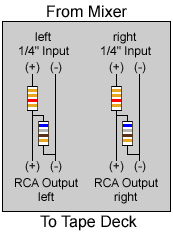
To build it, drill four holes in the project case; 2 for the 1/4" jacks, and 2 for the RCA's.
Solder the resistors in place on the circuit board, with enough wire to make the connections
to the jacks. After you've made all the connections, mount the jacks in the case,
then place the circuit board in the case, fasten the bottom, and you're all set!
It's a very basic circuit. It might seem wierd to some folks; the way you bring the positive
lead through the second resistor and then to ground. But it works!
If you wanted to get fancy, I suppose you could place some potentiometers (variable resistors)
in place of the resistors so you could fine-tune the pad level... I never found the need to.
Also, I suppose you could replace the two RCA's with a 1/8" stereo jack those of you with
walkman-style decks. |
I hope this has been helpful. If you have any questions or comments
just send me an email.
|
|
|
